Escort Configurator now offers a new way to build a calibration table: 3D tank calibration. As before, you can create the table without filling the tank with fuel, but now it is calculated from a volumetric model of your actual tank rather than from one of three standard formulas.
The new mode complements and extends the mathematical calibration added to Escort Configurator in January 2025. It is designed for cases where a formula produced a noticeable error: fuel tankers with an oval cross-section, tanks with rounded corners, storage tanks with a wide manhole or installed at an angle, as well as non-standard shapes such as saddle and stepped tanks. The previous mode is still available: when you launch the Configurator, you choose which calculation method to use.
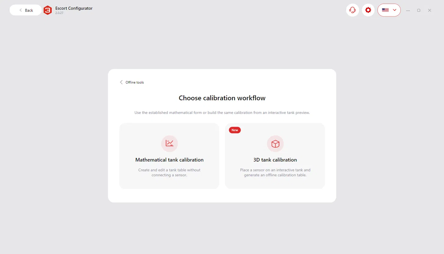
How mathematical calibration worked
Tank calibration is the most time-consuming stage of installing a fuel level sensor. Mathematical calibration cut it down to a couple of minutes: the user selected the tank type, entered its dimensions and the sensor dimensions, and the app calculated the table using a formula.
There were three formulas: for a rectangular tank, for a cylinder with flat ends and for a cylinder with torispherical heads. A real tank had to be approximated as one of these shapes, and any deviation from the ideal geometry reduced accuracy: dents, stiffening ribs, baffles, chamfered corners. That is why the mode was recommended mainly for large tanks that are difficult to calibrate by filling.
3D calibration removes this limitation: you no longer need to force your tank into a standard shape. You build a model that matches the real tank and immediately see what it looks like and how fuel is distributed inside it.
Complex tank shapes
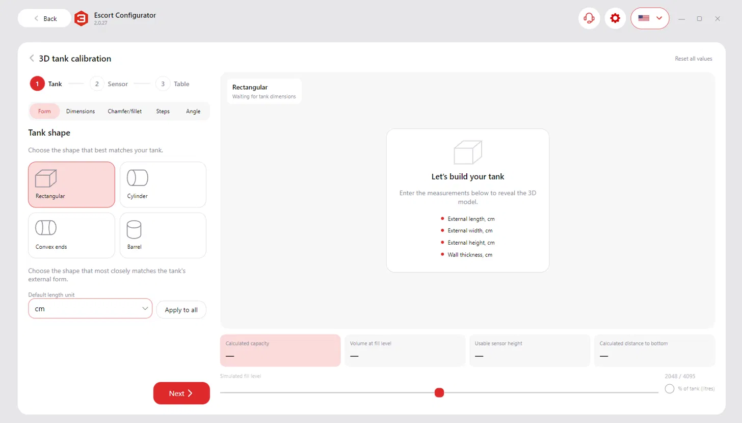
The model is built in three steps: Tank, Sensor, Table. First, choose a base shape: rectangular tank, cylinder, cylinder with dished ends or barrel. Then enter the dimensions and wall thickness. Take the dimensions from on-site measurements, not from the datasheet: the accuracy of the table depends directly on them.
You can enter dimensions in whatever way is easiest to measure them. The External / Internal switch defines whether you are entering the outer dimensions of the tank or the dimensions of its inner cavity. Units are selectable too: centimeters, millimeters, feet and others. On the Tank step you set the default units, and the Apply to all button converts every field at once. No more converting measurements by hand.
Rounded and chamfered corners
Most fuel tanks do not have sharp corners: they are rounded or chamfered, which used to cause errors. Now you can set an individual offset for each of the 12 edges, separately for the top, bottom and vertical edges. With the Chamfer option enabled, the edge is cut straight; without it, the edge is rounded.
The app shows how to measure the offset: place a carpenter’s square against the edge and measure the distance from the corner of the square to the point where the rounding begins.
Elliptical fuel tankers
Fuel tanker tanks often have an oval rather than a round cross-section, which the cylinder formula did not take into account. Now you just tick Different width and height and enter both dimensions. For a cylinder with dished ends, the head depth is specified separately. By default, the app uses 12% of the length between the weld seams, but it is better to measure it on site.
Saddle and stepped tanks
Some tanks cannot be reduced to any base shape: saddle tanks with a recess in the middle, stepped tanks and other tanks with ledges. For them, the rectangular tank now has a Steps tab that lets you cut rectangular sections of the required size out of the model. This way you can build virtually any shape made of flat faces, and the app instantly recalculates the volume and shows how fuel is distributed in such a tank.
Manholes on stationary tanks
On stationary tanks and tankers, the sensor is often installed through a manhole, and sometimes it is very large. The manhole holds fuel too, and it also raises the sensor mounting point. The new mode takes the manhole into account more accurately.
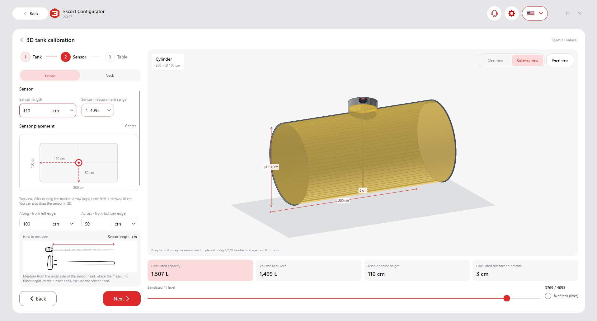
The Sensor step now has a Manhole tab. Here you enter the outer diameter and the internal height of the manhole, that is, the distance from the inside of the tank’s top wall to the platform on which the sensor is mounted. The app adds the manhole volume to the tank volume and recalculates the sensor position.
In a real-world comparison, a professional fill calibration of a tank, carried out to produce a millimeter-resolution calibration table, measured its volume at 7,013 L. 3D calibration based on measurements provided by the customer gave 7,016 L.
The difference between the two methods was only 3 L, or about 0.04% of the total tank volume, which shows that the results are comparable.
Tilted installation and sensor position
Stationary tanks are often installed with a slope towards the drain valve so that the remaining fuel is easier to drain. In a tilted tank, fuel is distributed differently than in a level one, so the same level corresponds to a different volume. In 3D calibration, the Tilt tab lets you set an angle from 0 to 45° and the direction of the rise. The model immediately shows how the fuel settles: at a 15° slope it collects at the lower end of the tank.
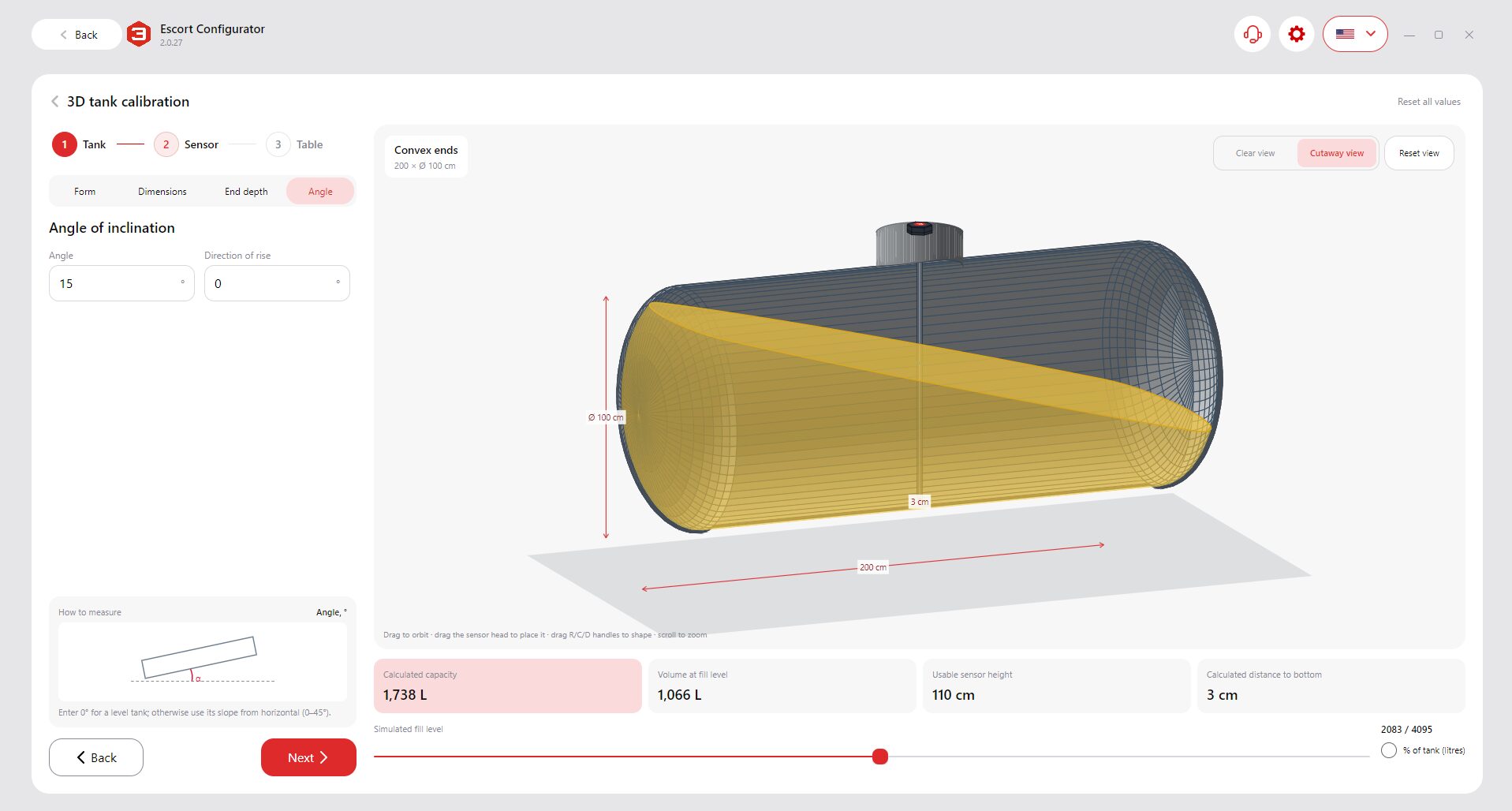
With a tilt, the sensor position matters too. In a level rectangular tank, the mounting point has almost no effect on the result. In a tilted tank or a tank with dished ends, however, the level under the sensor depends on where the sensor is installed. That is why you can place the sensor precisely on the model: click on the top view, nudge it with the arrow keys in 1 cm steps (10 cm with Shift), drag it in the 3D view or enter its coordinates from the left and bottom edges.
The app then checks the installation. It calculates the distance from the tube ends to the bottom and reminds you that a gap of at least 1.5 cm is needed for fuel to flow freely. It also shows how much fuel will remain below the tubes, outside the measuring range. In the example, this is 133.2 liters, or 4.5% of the tank. Previously, this could only be discovered after installation.
Smart placement of calibration points
On the final step, you only need to specify the number of table rows, from 2 upwards. The app selects the spacing between points automatically, and the spacing is non-uniform: there are more points where the volume changes most sharply with the level.
Why this matters: between the table points, the volume is calculated linearly. In the middle section of a cylinder or rectangular tank, the volume grows almost uniformly, so few points are needed. Near the bottom, under the top, in the heads and at rounded corners, however, it changes non-uniformly, and with equal spacing this is where the error is greatest. Placing more points in these zones makes a table of the same size noticeably more accurate.
If the full tank volume is known precisely, for example from a verification certificate or a fill test, you can enter it in the Measured full volume field, and the app will fit the table to this figure. The field is optional.
The finished table is saved as a CSV file. You can view it as a list or a chart, add rows manually and send it. The chart clearly shows that the points are dense at the edges of the range and sparser in the middle.


Visual feedback
Mathematical calibration produced a table but did not show where the numbers came from. In 3D calibration, the model is rebuilt with every change in dimensions, so a measurement error is visible immediately: if the model does not look like the real tank, one of the numbers is wrong.
You can rotate, zoom and view a cross-section of the model. The Fill level simulation slider fills the model with fuel up to the selected level. Four values are always displayed below the model: tank volume, volume at the selected level, sensor working height and distance from the tubes to the bottom. Each parameter has a How to measure tip with a diagram.
This visualization is useful not only for installers. A model showing the tilt, the manhole and the zone below the tubes makes it easy to explain to a customer why the table looks the way it does and why part of the fuel is not visible to the sensor.
Download the latest version of Escort Configurator and try the new mathematical calibration mode in practice.
